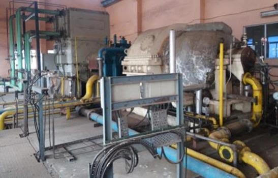
10 MW Siemens (2006) make Condensing type Steam Turbine Generator Set,
10 MW Siemens (2006) make Condensing type Steam Turbine Generator Set, having the Following Technical Specifications:
TECHNICAL DETAILS:
TURBINE DETAILS:
Manufacturer : Siemens (India)
Year of Make : 2006
RatedPower(At generator terminals) : 10000 kW
Speeds
Turbine Speed : 7500 RPM
Emergency trip(Turbine) : 8250 RPM
Critical Speed - 1 : 2850 RPM
Critical Speed 2 : 6000 RPM
Direction of Rotation : C.C.W.
Steam Parameters:
Inlet Steam Pressure : 64 Ata
Inlet Steam Temperature : 480° C
Inlet Steam Flow : 42.0 t/h
Bleed Steam Pressure : 4.406 Ata
Bleed Steam Temperature : 207.3° C
Bleed Steam Flow : 5.312 t/h
Exhaust Steam Pressure : 0.104 Ata
Speed
Rated(Generator) : 1500 RPM
GEAR BOX DETAILS:
The supplied Gearbox is a Reducer type gearbox, which is designed with a service factor in accordance with AGMA 6011 H-98, The high speed shaft of the gearbox in coupled to the turbine by means of a flexible coupling. The low speed shaft end of the turbine is coupled directly to the alternator. Torque is transmitted at the low speed end due to Frictional force generated by the butting of the two shafts.
Manufacturer : Triveni
Type : N2419C
Rated power : 10000 kW
Year of make : 2006
Input Speed (Turbine) : 7500 RPM
Output Speed (Generator) : 1500 RPM
Speed ratio : 5: 1
Lubrication
Oil Type : ISO VG 46
Filtering : 25 microns
Inlet Pressure : 1.5 to 2.0 Bar (g)
Inlet temperature : 48° C
Oil Flow : 240 LPM
Barring Gear
Type : Manual engage and auto disengage
Power : 11 kW
RPM : 1470
Instrumentation
Provision for Vibration probes (3/4” NPT) supplied with XL-Type probes for radial bearing & Axial Bearing
Thermo Elements
Temperature Probes (PT 100, 2x3 wire)
Vibration measuring (see Section 2.7 Special Instrumentation)
Main Oil Pimp
Flow : 700 LPM
Discharge pressure : 5 bar
ALTERNATOR DETAILS:
Manufacturer : TDPS, Bangalore
Type : TC-145
Year of make : 2006
Capacity : 10 MW
Voltage : 11 kV ± 10%
Current : 656 A
Power Factor : 0.8 Lag
Frequency : 50 Hz ± 5 %
Speed : 1500 RPM
Critical Speed (with respect to turbine) : 2250 RPM
Protection : IP54
Cooling Water Inlet Temperature : 36° C
Air inlet temperature : 45° C
Oil Quantity : ISO VG46
Oil Inlet temperature : 49° C
Oil Outlet Temperature : 64° C
CONDENSING SYSTEM DETAILS:
Purpose of System
The purpose of the condenser and evacuation system is
To build up and maintain a necessary vacuum for the turbine exhaust steam.
To condensate exhaust steam flow from the turbine.
To perform vacuum braking and shorten the turbine coasting down time.
To receive internal drainage from the turbine plant and this way return it to the process.
System Function
The main condenser is a tube heat exchanger, Exhaust steam from the turbine is condensed in the tube bundle and the condensate is collected in the Condenser hotwell, the condensate level controlled and always kept below the tube bundle. Subcooling of the condensate is prevented by the design.
The purpose of the vacuum- breaking valve to reduce the condenser vacuum by admitting air to the condenser and tube casing.
A rupture disc in the condenser shall prevent in the turbine exhaust and condenser system.
With turbine internal drain lines flash tank is connected to condenser hotwell.
Manholes for internal inspection are provide on the water boxes and the condenser shell.
Condenser:
Manufacture : Siemens Ltd
Operating Pressure : 0.105 ata
Operating temperature : 46.4 Deg. C
Test Pressure Shell side : Water Filled
Test Pressure Tube Side : 6.5 bar (g)
Weight of the equipment (empty) : 22000 KGS
Weight of the Equipment (Operating) : 34000 KGS
Weight of the Equipment (flooded) : 42000 KGS
Steam Jet Air Ejector:
Condenser vacuum is built up and maintained with a steam jet air ejector unit.
A high capacity steam Ejector (Hogging ejector) is used to build up the vacuum in the main condenser during starting procedure.
During operation in the two stage steam ejector is used to maintain the condenser vacuum operating steam is condensed in the stages of the ejector condenser, which is cooled by condensate from the main condenser (inter condenser) Air and other non-condensed steam are then evacuated from the second stage.(after condenser)
Main Components:
Hogger ejector with silencer
Y Stage Ejector I
Y Stage Ejector II
Z Stage Ejector I
Z Stage Ejector II
Motive steam Pressure and temperature are 10Ata and 400° C
Steam Jet Ejector supplied by new field for details please refer manual
Condensate Extraction Pumps:
Condensate extraction pumps are supplied by Sulzer.
PROTECTION AND SAFETY EQUIPMENT (Emergency Tripping):
Sr. No.Criterion Unit range Operating range Response 1.Over speed Turbine Min17500 82502. Ax. Bearing position Mm± 0.1 to 0.36± 0.83.Turbine bearing metal temperature ° C60 to 90° C>1254.Turbine bearing vibration Microns 55 >1055.Lube oil pressure Kg/cm2 2.5 <1.26.Turbine exhaust steam pressure Ata 0.104>0.47.Exhaust temperature ° C55>1058.Generator bearing metal temperature ° C60 to 70>9012.Generator bearing vibration Microns130>23210.Gear box radial bearing Temperature ° C60 to 80 >11011.Gear box vibrationMicrons50(HS)
60(LS)>125
>15012.Generator winding temp° C80 to 90>14513.Inlet steam pressure Bar 64>69.3
<28.414Inlet steam temperature ° C480>494
<280
PROTECTION AND SAFETY EQUIPMENT (Alarm Signal):
Sr. No.Criterion Unit range Operating range Response 1.Turbine bearing metal temperature° C60 to 90° C>1202.Axial bearing position Mm± 0.1 to 0.2± 0.63.Turbine bearing vibration Microns 55 >704.Oil temperature after lube-oil filter° C48>55
<305.Oil pressure difference at Lube oil filter Bar0.8>0.86.Lube oil header Bar(g)2.5<1.77.Pressure difference at control oil filterBar0.2>0.88.Inlet steam pressure Bar64.0>66.15
<56.79.Inlet steam temperature° C480>488
<35010.Exhaust steam pressureAta0.104>0.611.Exhaust steam temperature° C55>8512.Seal Steam pressure Bar0.02<0.005
>0.05
>85
13.Generator bearing metal temperature° C60 to 70>8514.Generator winding temp° C80 to 90>14015.Generator hot air temperature ° C60 to 70 >8016.Generator cold air temperature° C40 to 45>52
17.Gear box vibrationMicrons60(LS)
50(HS)>90
>6518.Generator winding temp° C60 to 80>10019Generator bearing vibration Microns130>180
SCOPE OF SUPPLY:
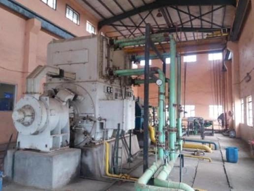
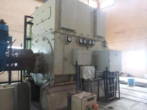
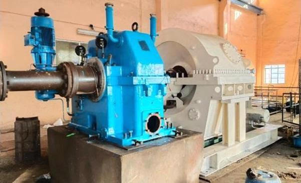
1 No. 10 MW SIEMENS make steam turbine coupled to TRIVENI make reduction gear box and 10 MW TDPS make alternator.
Inlet Steam Valve.
3) Complete governing system with actuator &all interconnected pipings.
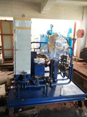
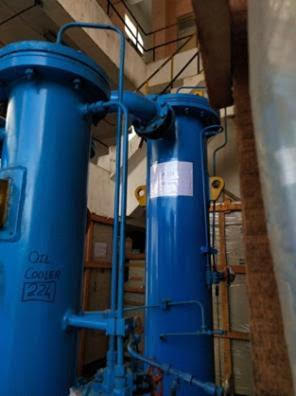
4) Complete oil cooling system including:
a) Oil tank with AOP mounted on the tank, Oil Vent, etc. with interconnected oil piping.
b) Oil skid comprising of 2 Nos. Oil Coolers with 1 Set of duplex Oil Filters, 2 Nos. Control Oil Coolers with 1 Set of duplex Oil Filters and all interconnecting oil pipeline.
c) Main oil pump mounted on gearbox shaft.
d) Oil Centrifuge with all interconnecting piping.
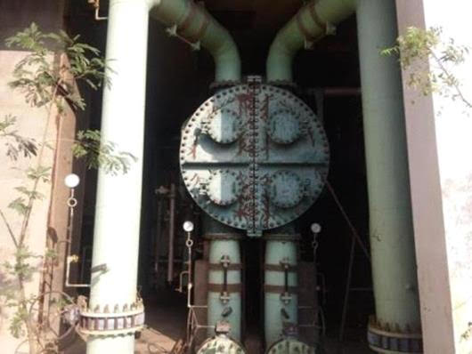
5) Complete condensing system including:
i) Bellow mounted between turbine and condenser.
ii) Condenser with spring mounted supports (4 Nos.) complete with its mountings, bellows, condenser flashbox, etc.
iii) 2 Nos. Condensate extraction pumps with electric motors.
6) Air Ejector system with valves.
7) Turbine Supervisory Panel (including 505 Governor).
8) Gear box with its mountings, auxiliaries and pedestals.
9) Coupling between turbine & gear box and gear box & alternator.
10) Alternator Cooling System (Mounted on alternator top).
11) Exciter with its pedestal (mounted separately).
12) 1 No. AVR panel.
13) 1 No. 10 MW 11 kV generator panel.
14) 1 No. NGR panel.
15) 1 No. CT/PT Panel.
16) 1 No. 110/11kV Transformer Panel (Ring Panel).
17) 1 No. Float cum Boost Charger Panel.
18) 1 No. Turbine MCC Panel.
19) All locally mounted controls.
20) Cables from alternator/exciter up to control panel.
21) Interconnecting pipings between all the TG Set accessories, as available.
22) Manuals & Drawings pertaining to the turbine, gear box and alternator, as available.
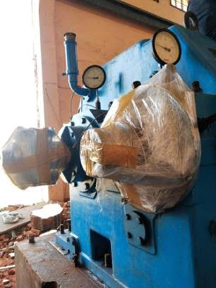
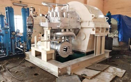
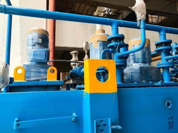
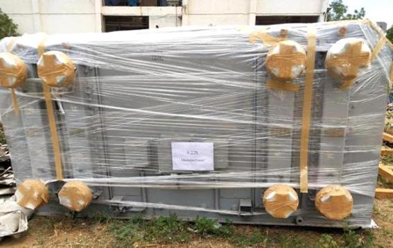
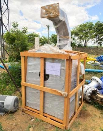
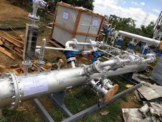
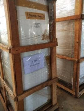
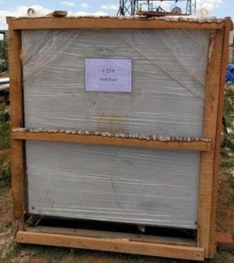
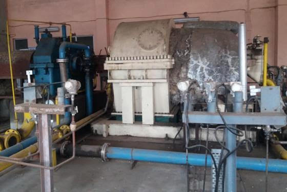
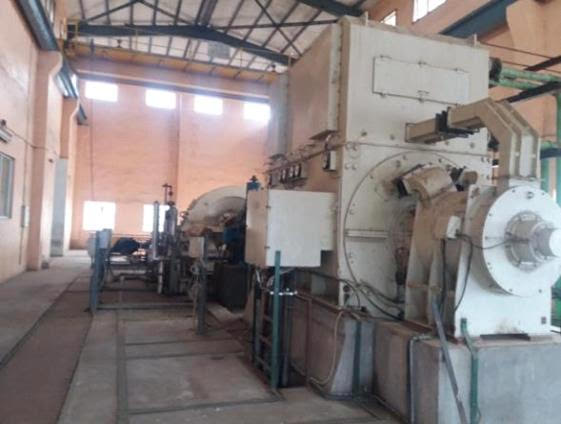
PHOTOGRAPHS:

 Aircraft
 Business Opportunities / Investments
 Chemicals
 Clearance/Liquidations
 Commodities ( Rice, Sugar , Soy Grains, Minerals and Ore)
  Fire/Rescue/Medical
 Food/Beverages
  Housing
 Military Equipment/Unrestricted
 Military/Police
 Pet Supply
 Petroleum Product
 Plant and Equipment
 Recyclable-HMS-PVC
 Ships/Vessels/Boats
 Solar/Wind-Power
 Vehicles
 Wanted
 Zoo supply (unrestricted )