4 GE TM2500 GEN8 TRAILER MOUNTED GENERATOR PACKAGES
4 GE TM2500 GEN8 TRAILER MOUNTED GENERATOR PACKAGES
offer for 4 TM 2500 units.
These are expected to sell VERY fast
Proposal for Supply of 4 x TM2500
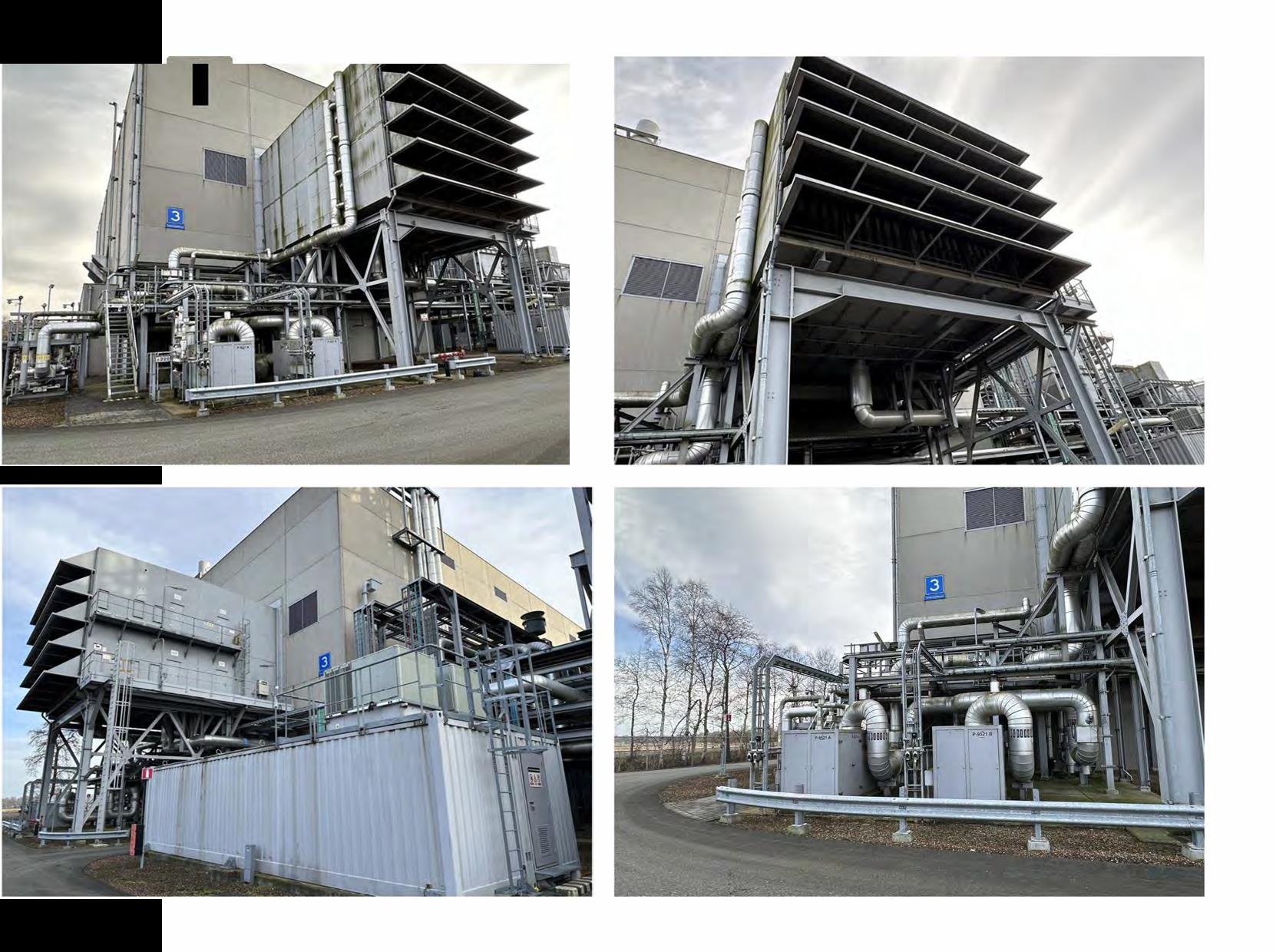
EQUIPMENT DESCRIPTION
GE TM2500 Mobile Gas Turbine Generator Sets Each TM2500 consists of two trailers and auxiliary equipment. The trailers include the main trailer and auxiliary trailer. The inlet air filter assembly and exhaust duct assembly ship loose and are assembled onto the main trailer during commissioning. In addition to the above, Seller will ship spare parts and tools as required.
YOM: 2014
Hours: less than 5000
Output: 30.9 MW @ 60 Hz (ISO) 26.3MW @ 50Hz (ISO)
Dual frequency: 50/60 Hz
Full Power in <10 minutes
Dual fuel: Liquid or Natural Gas fuel capability
Small Footprint
Package serial no
Model No Mftg Date Hours Location
XXXXXX TM2500+ 2014 4900+/
XXXXXX TM2500+ 2014 4900+/-
XXXXXX TM200+ 2014 4900+/-
XXXXXX TM200+ 2014 4900+/-
SCOPE OF SUPPLY
TM2500+ GEN 6/7 GE Mobile Gas Turbine 60/50Hz
II. SCOPE OF SUPPLY Main Trailer Consisting of the following components:
Main Trailer and Jeep A seven-axle, air ride suspension trailer (3+4) and a 3-axle jeep are used to transport the main trailer components. The trailer and jeep combination is approximately 108 (32.9m) long (less tractor) during transport and weighs approximately 210,000 pounds (95,254 kg) fully loaded. Ten landing legs are provided to support and level the equipment at the jobsite.
Gas Turbine The gas turbine is a General Electric LM2500 PKMDW model ISO rated for continuous duty and configured for operation on either natural gas or liquid fuel. Each is configured for optional water injection for NOx reduction, if required. The engine is shock mounted for shipping and shipped in position, with the exception of the coupling spacer, which is installed during commissioning.
Fuel System Dual Fuel Configuration Natural Gas fuel system using an electronically controlled fuel metering valve. For full-load operation, the gaseous fuel must be supplied to the Auxiliary Trailer skid connection at: 320 MMBtu/hr Max; 180 °F [82 ° C]; Max; 520 +/- 20 PSIG (3,585 +/- 138 kPaG); and filtered to 5 or less Microns.
Liquid fuel system; Typical liquid fuels include DF1, DF2, or JP4. For full-load operation, buyer must supply liquid fuel to the connection at the Auxiliary Trailer Skid at 40 GPM (151.4 L/min], 30 ± 10 PSIG (207 ± 69 kPaG], filtered to 5 Microns and at least 20°F (11°C) above the wax point temperature.
All necessary shutoff valves, flow meter, piping and instruments between the Auxiliary Trailer Skid connection and the engine are included. Buyer must provide supply piping with sampling ports, fuel system filtration and applicable shut-off valves and containment per local codes and standards.
Water Injection System Capable of water injection for NOx reduction. For full-load operation, the demineralized water must be supplied to the Auxiliary Trailer Skid connection at 28 GPM (106 L/min], 15 PSIG (103 kPaG] Minimum, 40 to 140 °F (4 to 60 °C) filtered to 10 Microns. The buyer must provide demineralized water that is clean, filtered and compliant with General Electric specification MID-TD-0000-3.
Switchgear Supplied with a 3 section NEMA 3R switchgear enclosure, including a set of generator circuit breaker equipment, 2 sets of incoming line voltage monitoring equipment, a marshalling cabinet and a set of switchgear accessories. Permanent cable terminations from the neutral and line-side of the generator are also included.
Auxiliary Trailer Skid The Auxiliary Trailer Skid includes fuel and water injection system components not mounted on the main trailer. The pumps, filters and necessary instrumentation are connected to the main trailer components at site with interconnect hoses. The Auxiliary Trailer Skid also includes the hydraulic start system and water wash system described below.
Electro-Hydraulic Start System Supplied with a hydraulic starting system, which includes an electric motor driven hydraulic pump assembly, filters, and a fin/fan heat exchanger mounted on the auxiliary equipment module. A hydraulic motor is also mounted on the gas turbine accessory gearbox to turn the gas generator shaft. All piping and fittings on the base plates, plus hydraulic connections between the auxiliary equipment module and the main base plate are also furnished.
"Off Line" Soak Wash System An "off-line" cleaning system, with a water wash reservoir and all necessary filters and instrumentation supplied.
Fire Protection System Installed fire protection system complete with hydrocarbon sensing and thermal detectors, piping and nozzles in the engine compartment. The fire protection system includes cylinders containing CO2 mounted on the Auxiliary Trailer. An included 24 VDC battery and charger powers the fire protection system (located in the control house.) All alarms and shutdowns are annunciated at the unit control panel. An alarm sounds at the turbine if the gas detectors detect high gas levels, or if the system is preparing to release the CO2. When activated, the package shuts down, and the primary CO2 cylinder is discharged into the turbine compartment via multiple nozzles, and the ventilation dampers automatically close. After a time, delay and if required, the reserve supply of CO2 is discharged.
Fin Fan Cooler A 100% redundant dual fan, single core cooler with separate coils for the turbine, generator lube oil and hydraulic oil. The cooler is equipped with all interconnect piping and instrumentation necessary for the three circuits.
Control House The basic equipment package is supplied with a lighted, insulated 22 (6.7 m) long by 8-6" (2.6 m) wide control house. The control house is equipped with an access door, air conditioner/heater, and a hand held fire extinguisher. The control house is used to package the equipment listed below.
Digital Control System The control system features an integrated electronic fuel management system with a programmable sequencer, vibration monitor, fire system monitor, digital meter, and a digital generator protective relay module. A desktop or laptop PC with separate workstation and chair is provided for HMI control. Alarm and shutdown events are displayed on the HMI automatically. A dedicated 24V DC battery system with power charger is included in the control house.
Generntor Protective Relays The equipment package is supplied with two (2) Integrated Generator Protection System (IGPS) microprocessor-based relay modules, mounted in the turbine control panel. One IGPS is configured for 50Hz and one IGPS is configured for 60Hz. The appropriate IGPS will be selected for use at Site. The IGPS includes all functions necessary for protection of the generator.
Unit Motor Control Center A freestanding lineup of motor controls for all TM2500+ package motors is supplied. The motor control center is installed in the control house and also includes a 45 kVA lighting and distribution transformer.
Battery and Charger System The equipment package is supplied with a 24 VDC NiCad battery system for control power and fire system and charger for each. In addition a 125 VDC NiCad battery system with charger is supplied for the generator lube pump. The 125VDC battery charger has a selector switch to receive power from either the MCC or an external generator to charge the batteries. The battery systems are fully wired and mounted in racks and are installed in the control house along with the wall-mounted chargers.
Gas Turbine Air Filter Assembly The air filter is approximately 27 (8.2 m) long and 10-11" (3.33 m) wide and weighs approximately 20,000 pounds (9072 kg) fully loaded. The air filter is equipped with a two-stage filtration system for both ventilation and combustion air with panel type pre-filters housed in hinged doors and high efficiency barrier filters. The air filter includes weather hoods installed in front of the filtration system and inlet silencers. An inlet plenum with hatch is provided for access to the FOD screen for maintenance. Ventilation fans for the turbine enclosure are installed in the air filter assembly. Two 50% fans and a bypass damper are installed. All of the items listed are housed in the filter house that is complete with an access door for maintenance, separate air paths and turning vanes and the necessary instrumentation. For connection to the Main Trailer, the air filter is hard mounted directly on top of the combustion and ventilation inlet plenum.
COMMON TERMINAL POINTS
Combustion Air: Inlet face to air inlet filter house
Exhaust: Exit from the gas turbine exhaust stack
Fuel: Inlet flange to the gas turbine on base fuel system (fuel to be supplied clean filtered and compliant to GE Specifications)
Cooling system: Water filling connection on the fin-fan cooler header tank
Lube oil: Make up flange connection on the gas turbine on-base reservoir
Ventilation: Inlet/outlet grilles on unit enclosure
Drains and vents: On-base flange/connections lube oil vent outlets, gas vent outlets
Electrical (HV): High Voltage outgoing terminals of High voltage switch (voltage to be confirmed once know and transformers ordered accordingly)
Electrical (LV): LV power terminals on the auto-changer panel standby supply and junction box (external interfaces by others)
Control System: Control terminals on each junction box for external interfaces by others
Earth Grid: Earthing points located on and around equipment skids
DELIVERY AND INSTALLATION
The 4 units are available for immediate shipment from their site.
**Inspection, borescope & removal is to be paid by the Seller
Unit availability is subject to prior sale and due to the versatility of these types of units availability can change very quickly.
We are pleased to offer our services for the installation of these units if needed.
PRICING AND PAYMENT SCHEDULE
Supply of the above-mentioned equipment as per scope of supply. Pricing does not include any taxes duties or government charges. Any diversion from scope of supply as stated in this proposal could incur a price change.
All pricing is in United States Dollars
QTY 4
Description TM2500 GEN8 GE Mobile Gas Turbines
Unit price $29.500,000
Total Price $118.000.000
Payment schedule
$1.000.000 per unit deposit into escrow to secure the units before inspection Remainder paid within 15 days after inspection and before removal of any equipment.
All payments are to be made via electronic wire transfer.
I trust that this proposal meets your satisfaction and look forward to your favorable reply. 26th August 2025
#sch


 Aircraft
 Business Opportunities / Investments
 Chemicals
 Clearance/Liquidations
 Commodities ( Rice, Sugar , Soy Grains, Minerals and Ore)
  Fire/Rescue/Medical
 Food/Beverages
  Housing
 Military Equipment/Unrestricted
 Military/Police
 Pet Supply
 Petroleum Product
 Plant and Equipment
 Recyclable-HMS-PVC
 Ships/Vessels/Boats
 Solar/Wind-Power
 Vehicles
 Wanted
 Zoo supply (unrestricted )